It’s usually easy enough to draw a coordinate grid on your project in the current coordinate system. But what if you need to draw a latitude longitude or other coordinate system grid. The lines and labels aren’t ortho anymore nor is the spacing the same (or even consistent).
This tool draws a bound collection of grid lines (and labels) in any alternate coordinate system. Simply select the alternative system and window off the clipping (ortho) rectangle in the drawing and specify the interval.
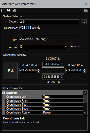
Other Parameters: This section give you full control over whether labels are place on the left, right, bottom, top, etc. You can control the layer and colors, tic mark sizes, and more.
When all parameters are specified, clicking the [Save] button draws the grid content as model space geometry (no layouts required). In the example below, the drawing of this area is state plane coordinates (feet) and a latitude longitude grid was drawn. You will notice the vertical grid line spacing is larger than the horizontal. Even though the latitude lines look horizontal (at this scale), there is actually a fifty five feet difference in the vertical coordinates.
At any time you need to change the size of the grid or simply change a parameter, you can launch this tool again and open the grid for editing, make changes and update with the next save button click!
This tool is available in: