It’s a common occurrence to receive a drawing from outside sources that do not have a coordinate system assigned. This value is easy to check at the command prompt using the CGEOCS system variable, which shows “” (blank) when the system has not been assigned.
When you find this case and review the coordinates of the drawings, many times you can determine it has large values (in the hundreds of thousands or more) and may likely be a known system, but which system?
We had seen this case occur and set out to provide a solution and the result can often obtain the result in less than a minute, instead of hours!
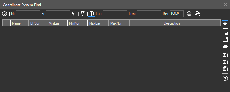
When the Projections > Find System dialog first appears it looks like this. The following procedure will show how quick and easy it is to find the system when you know geographically where the site is and you could pick it out in GE (Google Earth).
- Launch the Projections > Find System tool from the menu, ribbon or PrjFndSys command.
- At this step all we need is a point in the drawing and a latitude and approximate longitude. Click the Arrow with + button (right of N/E fields) and pick a prominent (easily distinguishable) point in the CAD drawing.
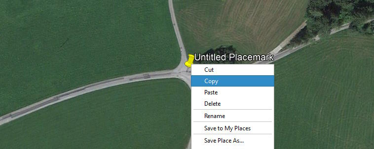
- Switch to GE and zoom and pan to that same point, click the Add Placemark button and optionally give it a name. Then right click on the placemark and choose copy (like the image below).
- Return to CAD where our dialog was open and the lat/long will be inserted into the fields as soon as it receives focus!
At this point your dialog shows the map coordinates and lat/lon for the (same) point. All we need is a distance tolerance, the maximum distance (in drawing units) that the point can be away from the drawing point picked. A reasonable starting value is 50 feet or 15 meters, too small and it won’t find anything. Now you’re ready to search the database of named systems.
Clicking the COG (gear) icon near the end of the top toolbar causes the tool to begin searching and the grid will fill with any qualifying systems. There are thousands of systems but your list will be small because of the location filter.
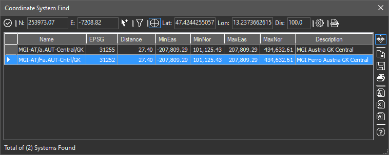
When multiple records appear it’s time to narrow it down. With the [+] icon on the top of the vertical toolbar selected, as you select a row in the grid a new Placemark will appear in GE. Selecting a different row causes GE to pan to and show the new location of the Placemark.
When you are satisfied with the location and have a row selected, simply click the checkmark icon in the dialogs upper left corner and the system will be assigned.
You can then use all the tools available in the our Projections section or push the drawing geometry into GE using our Tools > Drawing Publish tool.